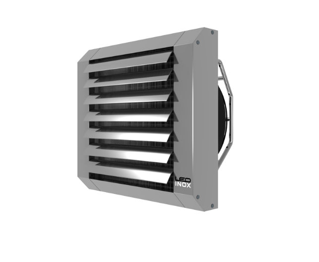
Fan heater designed for indoor installation.
Casing made of stainless steel ensures resistance to corrosion. To maintain its anti-corrosive properties it has to be kept clean.
Console made of stainless steel enables the installation of the unit on vertical and horizontal partitions and also on tight columns. It enables the user to install the heater parallel or at different angles to the wall.
.
LEO INOX is designed for heating the buildings with medium and big cubatures. They are suitable for operation in high humidity, so they can be installed in food industry buildings, gastronomic buildings, greenhouses etc.
Casing – made of stainless steel ensures resistance to corrosion.
Console – make installation of the unit on horizontal and vertical partitions, parallel or at the angle of 30o or 45o to the wall possible.
| LEO INOX 25 V | LEO INOX 25 M | LEO INOX 45 V | LEO INOX 45 M | LEO INOX 65 V | LEO INOX 65 M | |
| Max. air flow [m3/h] | 4400 | 4400 | 4100 | 4100 | 3900 | 3900 |
| Max. air flow range [m]* | 26 | 26 | 24 | 24 | 22 | 22 |
| Power supply [V/Hz] | 230 / 50 | 230 / 50 | 230 / 50 | 230 / 50 | 230 / 50 | 230 / 50 |
| Max. current consumption [A] | 1,4 | 0,7 | 1,4 | 0,7 | 1,4 | 0,7 |
| Max. power consumption [W] | 320 | 170 | 320 | 170 | 320 | 170 |
| IP / Insulation class | 54 / F | 54 / F | 54 / F | 54 / F | 54 / F | 54 / F |
| Max. acoustic pressure level [dB(A)]** | 54 | 51 | 54 | 51 | 54 | 51 |
| Max. heating water temperature [oC] | 130 | 130 | 130 | 130 | 130 | 130 |
| Max. operating pressure [MPa] | 1,6 | 1,6 | 1,6 | 1,6 | 1,6 | 1,6 |
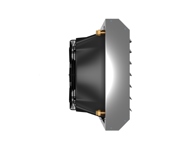
| Hydraulic connection ["] | ¾” | ¾” | ¾” | ¾” | ¾” | ¾” |
| Max. operating temperature [oC] | 60 | 60 | 60 | 60 | 60 | 60 |
| Weight [kg] | 19,4 | 16,1 | 20,8 | 17,5 | 22,7 | 19,4 |
| Weight of unit filled with water [kg] | 20,4 | 17,1 | 22,8 | 19,5 | 25,4 | 22,1 |
* Range of horizontal, isothermal air stream at 0,5 m/s speed limit.
** Acoustic pressure level at a distance of 5 m from the unit, in the room of medium capabillity of sound absorption and 1500 m3 of cubic measure.
| LEO INOX 25 | ||||||||||||||||||||
| Tp1 | PT | Qw | ∆pw | Tp2 | PT | Qw | ∆pw | Tp2 | PT | Qw | ∆pw | Tp2 | PT | Qw | ∆pw | Tp2 | PT | Qw | ∆pw | Tp2 |
| °C | kW | l/h | kPa | °C | kW | l/h | kPa | °C | kW | l/h | kPa | °C | kW | l/h | kPa | °C | kW | l/h | kPa | °C |
| Tw1/Tw2 = 90/70°C | Tw1/Tw2 = 80/60°C | Tw1/Tw2 = 70/50°C | Tw1/Tw2 = 60/40°C | Tw1/Tw2 = 50/40°C | ||||||||||||||||
| 1 (V = 2250 m3/h) | ||||||||||||||||||||
| 0 | 18,5 | 817 | 6 | 25,5 | 15,8 | 693 | 4,5 | 20,5 | 13 | 568 | 3,3 | 17 | 10,1 | 442 | 2,2 | 13,5 | 10,2 | 885 | 7,7 | 13,5 |
| 5 | 17,3 | 764 | 5,3 | 27,5 | 14,6 | 640 | 3,9 | 24 | 11,8 | 514 | 2,7 | 20,5 | 8,9 | 387 | 1,7 | 16,5 | 8,9 | 777 | 6,1 | 16,5 |
| 10 | 16,1 | 711 | 4,6 | 31 | 13,3 | 586 | 3,3 | 27,5 | 10,5 | 460 | 2,3 | 24 | 7,6 | 331 | 1,3 | 20 | 7,7 | 668 | 4,6 | 20 |
| 15 | 14,9 | 657 | 4 | 34,5 | 12,1 | 532 | 2,8 | 30,5 | 9,3 | 405 | 1,8 | 27 | 6,3 | 273 | 0,9 | 23 | 6,4 | 557 | 3,4 | 23,5 |
| 20 | 13,7 | 604 | 3,4 | 37,5 | 10,9 | 477 | 2,3 | 34 | 8 | 349 | 1,4 | 30,5 | 4,9 | 211 | 0,6 | 26 | 5,1 | 445 | 2,3 | 26,5 |
| 2 (V = 3400 m3/h) | ||||||||||||||||||||
| 0 | 23,3 | 1028 | 9 | 20,5 | 19,8 | 871 | 6,9 | 17,5 | 16,3 | 714 | 5 | 14 | 12,8 | 556 | 3,3 | 11 | 12,8 | 1114 | 11,7 | 11 |
| 5 | 21,8 | 961 | 8 | 24 | 18,3 | 803 | 5,9 | 21 | 14,8 | 646 | 4,1 | 18 | 11,2 | 487 | 2,6 | 14,5 | 11,2 | 978 | 9,2 | 15 |
| 10 | 20,2 | 893 | 7 | 27,5 | 16,7 | 736 | 5,1 | 24,5 | 13,2 | 578 | 3,4 | 21,5 | 9,5 | 417 | 2 | 18,5 | 9,7 | 840 | 7 | 18,5 |
| 15 | 18,7 | 826 | 6 | 31 | 15,2 | 667 | 4,2 | 28 | 11,6 | 509 | 2,7 | 25 | 7,9 | 345 | 1,4 | 22 | 8 | 701 | 5,1 | 22 |
| 20 | 17,2 | 758 | 5,2 | 34,5 | 13,6 | 599 | 3,5 | 31,5 | 10 | 439 | 2,1 | 28,5 | 6,2 | 271 | 0,9 | 25 | 6,4 | 560 | 3,4 | 25,5 |
| 3 (V = 4400 m3/h) | ||||||||||||||||||||
| 0 | 26,7 | 1179 | 11,6 | 18 | 22,7 | 999 | 8,8 | 15,5 | 18,7 | 819 | 6,3 | 12,5 | 14,6 | 637 | 4,2 | 10 | 14,7 | 1279 | 15 | 10 |
| 5 | 25 | 1101 | 10,2 | 22 | 21 | 921 | 7,6 | 19 | 16,9 | 741 | 5,3 | 16,5 | 12,8 | 558 | 3,3 | 13,5 | 12,9 | 1122 | 11,8 | 13,5 |
| 10 | 23,2 | 1024 | 8,9 | 25 | 19,2 | 843 | 6,5 | 23 | 15,1 | 662 | 4,3 | 20 | 11 | 478 | 2,5 | 17,5 | 11,1 | 963 | 9 | 17,5 |
| 15 | 21,4 | 946 | 7,7 | 29,5 | 17,4 | 765 | 5,4 | 26,5 | 13,3 | 583 | 3,4 | 24 | 9,1 | 396 | 1,8 | 21 | 9,2 | 804 | 6,5 | 21 |
| 20 | 19,7 | 868 | 6,6 | 33 | 15,6 | 686 | 4,5 | 30,5 | 11,5 | 502 | 2,6 | 27,5 | 7,2 | 312 | 1,2 | 24,5 | 7,4 | 642 | 4,3 | 25 |
| LEO INOX 45 | ||||||||||||||||||||
| Tp1 | PT | Qw | ∆pw | Tp2 | PT | Qw | ∆pw | Tp2 | PT | Qw | ∆pw | Tp2 | PT | Qw | ∆pw | Tp2 | PT | Qw | ∆pw | Tp2 |
| °C | kW | l/h | kPa | °C | kW | l/h | kPa | °C | kW | l/h | kPa | °C | kW | l/h | kPa | °C | kW | l/h | kPa | °C |
| Tw1/Tw2 = 90/70°C | Tw1/Tw2 = 80/60°C | Tw1/Tw2 = 70/50°C | Tw1/Tw2 = 60/40°C | Tw1/Tw2 = 50/40°C | ||||||||||||||||
| 1 (V = 1700 m3/h) | ||||||||||||||||||||
| 0 | 25,9 | 1141 | 5,6 | 45 | 22,2 | 974 | 4,3 | 38,5 | 18,5 | 807 | 3,2 | 32 | 14,7 | 639 | 2,2 | 25,5 | 14,3 | 1241 | 7,3 | 25 |
| 5 | 24,2 | 1068 | 4,9 | 47 | 20,5 | 901 | 3,8 | 40,5 | 16,8 | 734 | 2,7 | 34 | 13 | 564 | 1,8 | 27,5 | 12,6 | 1092 | 5,8 | 26,5 |
| 10 | 22,5 | 995 | 4,3 | 49 | 18,8 | 828 | 3,2 | 42,5 | 15,1 | 660 | 2,2 | 36 | 11,2 | 484 | 1,4 | 29,5 | 10,9 | 946 | 4,5 | 29 |
| 15 | 21 | 923 | 3,8 | 51 | 17,2 | 754 | 2,7 | 44,5 | 13,4 | 585 | 1,8 | 38 | 9,4 | 411 | 1 | 31 | 9,2 | 797 | 3,3 | 30,5 |
| 20 | 19,3 | 850 | 3,3 | 53 | 15,5 | 681 | 2,3 | 46,5 | 11,7 | 510 | 1,4 | 40 | 7,6 | 330 | 0,7 | 33 | 7,4 | 645 | 2,3 | 32,5 |
| 2 (V = 2800 m3/h) | ||||||||||||||||||||
| 0 | 35,7 | 1571 | 10 | 38 | 30,6 | 1345 | 7,7 | 32,5 | 25,5 | 1114 | 5,7 | 27 | 20,2 | 882 | 3,9 | 21,5 | 19,7 | 1716 | 13,1 | 21 |
| 5 | 33,4 | 1471 | 8,8 | 40 | 28,3 | 1244 | 6,7 | 35 | 23 | 1012 | 4,8 | 29,5 | 17,9 | 779 | 3,1 | 24 | 17,4 | 1512 | 10,4 | 23,5 |
| 10 | 31,1 | 1374 | 7,7 | 42,5 | 26 | 1142 | 5,7 | 37 | 20,8 | 910 | 3,9 | 32 | 15,5 | 675 | 2,4 | 26,5 | 15 | 1307 | 8 | 26 |
| 15 | 28,9 | 1273 | 6,7 | 45 | 23,7 | 1040 | 4,8 | 40 | 18,5 | 807 | 3,2 | 34,5 | 13 | 569 | 1,8 | 28,5 | 12,6 | 1100 | 5,9 | 28 |
| 20 | 26,5 | 1172 | 5,8 | 47,5 | 21,3 | 938 | 4 | 42 | 16 | 703 | 2,5 | 36,5 | 10,6 | 461 | 1,2 | 31 | 10,2 | 891 | 4 | 30,5 |
| 3 (V = 4100 m3/h) | ||||||||||||||||||||
| 0 | 45 | 1986 | 15,2 | 32,5 | 38,5 | 1693 | 11,7 | 27,5 | 32 | 1402 | 8,6 | 23 | 25,5 | 1110 | 5,9 | 18,5 | 24,9 | 2163 | 19,8 | 18 |
| 5 | 42,1 | 1958 | 13,4 | 35,5 | 35,6 | 1565 | 10,2 | 30,5 | 29,1 | 1273 | 7,2 | 26 | 22,5 | 980 | 4,7 | 21 | 21,9 | 1905 | 15,8 | 21 |
| 10 | 39,2 | 1730 | 11,8 | 38 | 32,7 | 1437 | 8,7 | 33,5 | 26,1 | 1144 | 6 | 29 | 19,5 | 849 | 3,6 | 24 | 18,9 | 1646 | 12,1 | 23,5 |
| 15 | 36,3 | 1603 | 10,3 | 41 | 29,8 | 1308 | 7,3 | 36 | 23,2 | 1014 | 4,8 | 31,5 | 16,5 | 717 | 2,7 | 27 | 15,9 | 1385 | 8,9 | 26,5 |
| 20 | 33,4 | 1475 | 8,8 | 43,5 | 26,8 | 1179 | 6,1 | 39 | 20,2 | 883 | 3,7 | 34 | 13,3 | 581 | 1,9 | 29,5 | 12,9 | 1122 | 6,1 | 29 |
| LEO INOX 65 | ||||||||||||||||||||
| Tp1 | PT | Qw | ∆pw | Tp2 | PT | Qw | ∆pw | Tp2 | PT | Qw | ∆pw | Tp2 | PT | Qw | ∆pw | Tp2 | PT | Qw | ∆pw | Tp2 |
| °C | kW | l/h | kPa | °C | kW | l/h | kPa | °C | kW | l/h | kPa | °C | kW | l/h | kPa | °C | kW | l/h | kPa | °C |
| Tw1/Tw2 = 90/70°C | Tw1/Tw2 = 80/60°C | Tw1/Tw2 = 70/50°C | Tw1/Tw2 = 60/40°C | Tw1/Tw2 = 50/40°C | ||||||||||||||||
| 1 (V = 1400 m3/h) | ||||||||||||||||||||
| 0 | 31,4 | 1384 | 5,6 | 66,3 | 27,1 | 1192 | 4,4 | 57,5 | 22,9 | 1001 | 3,4 | 48,5 | 18,5 | 806 | 2,4 | 39 | 17,3 | 1502 | 7,3 | 36,5 |
| 5 | 29,4 | 1300 | 5 | 67 | 25,2 | 1108 | 3,9 | 58 | 20,9 | 915 | 2,8 | 49 | 16,5 | 719 | 1,9 | 39,5 | 15,3 | 1332 | 5,9 | 37,5 |
| 10 | 27,5 | 1215 | 4,4 | 69 | 23,3 | 1023 | 3,4 | 59 | 19 | 829 | 2,4 | 50 | 14,4 | 630 | 1,5 | 40 | 13,4 | 1161 | 4,6 | 38 |
| 15 | 25,6 | 1132 | 3,9 | 68,5 | 21,3 | 938 | 2,9 | 59,5 | 17 | 742 | 2 | 50,5 | 12,4 | 538 | 1,2 | 41 | 11,4 | 989 | 3,5 | 39 |
| 20 | 23,8 | 1048 | 3,4 | 69 | 19,4 | 853 | 2,4 | 60 | 14,9 | 654 | 1,6 | 51 | 10,2 | 443 | 0,8 | 41 | 9,4 | 814 | 2,5 | 39,5 |
| 2 (V = 2400 m3/h) | ||||||||||||||||||||
| 0 | 46,9 | 2071 | 11,6 | 58 | 40,5 | 1780 | 9,1 | 50 | 34 | 1489 | 6,8 | 42 | 27,5 | 1197 | 4,8 | 34 | 25,9 | 2249 | 15,1 | 32 |
| 5 | 44 | 1943 | 10,3 | 59 | 37,6 | 1651 | 7,9 | 51 | 31 | 1360 | 5,8 | 43 | 24,4 | 1065 | 3,9 | 35 | 22,9 | 1992 | 12,1 | 33 |
| 10 | 41,1 | 1813 | 9,1 | 60,5 | 34,6 | 1521 | 6,8 | 52,5 | 28,1 | 1228 | 4,8 | 44,5 | 21,4 | 931 | 3,1 | 36 | 19,9 | 1731 | 9,4 | 34,5 |
| 15 | 38,1 | 1683 | 8 | 61,5 | 31,6 | 1390 | 5,8 | 53,5 | 25 | 1096 | 3,9 | 45,5 | 18,2 | 795 | 2,3 | 37,5 | 16,9 | 1468 | 7 | 35,5 |
| 20 | 35,2 | 1551 | 6,9 | 63 | 28,6 | 1257 | 4,9 | 55 | 22 | 961 | 3,1 | 47 | 15 | 654 | 1,6 | 38,5 | 13,8 | 1201 | 4,9 | 37 |
| 3 (V = 3900 m3/h) | ||||||||||||||||||||
| 0 | 65,5 | 2892 | 21,3 | 50 | 56,5 | 2481 | 16,6 | 43 | 47,3 | 2071 | 12,3 | 36 | 38,1 | 1659 | 8,6 | 29 | 36,1 | 3144 | 27,7 | 27,5 |
| 5 | 61,4 | 2712 | 18,9 | 51,5 | 52,3 | 2300 | 14,4 | 44,5 | 43,2 | 1889 | 10,4 | 37,5 | 33,8 | 1475 | 6,9 | 30,5 | 32 | 2781 | 22,2 | 29 |
| 10 | 57,3 | 2529 | 16,7 | 53 | 48,2 | 2116 | 12,4 | 46,5 | 38,9 | 1704 | 8,7 | 39,5 | 29,5 | 1288 | 5,4 | 32,5 | 27,7 | 2413 | 17,2 | 31 |
| 15 | 53,1 | 2344 | 14,5 | 55 | 44 | 1931 | 10,5 | 48 | 34,7 | 1517 | 7 | 41 | 25,2 | 1097 | 4,1 | 34 | 23,5 | 2042 | 12,7 | 32,5 |
| 20 | 48,9 | 2159 | 12,5 | 56,7 | 39,7 | 1744 | 8,8 | 50 | 30,3 | 1328 | 5,5 | 43 | 20,7 | 902 | 2,9 | 35,5 | 19,2 | 1667 | 8,8 | 34,5 |
1,2,3 - step
V – air flow
PT – heating capacity
Tp1 – inlet air temperature
Tp2 – outlet air temperature
Tw1 – inlet water temperature
Tw2 – outlet water temperature
Qw – water stream flow in the heat exchanger
Δpw – water pressure drop in heat exchanger
LEO INOX heaters can be installed in any position on the vertical or horizontal partitions in the buildings. For this purpose there is a specially designed installation console made of stainless steel, which enables the installation of the unit vertically, horizontally or at the angle of 30 or 45 degrees to the partition.
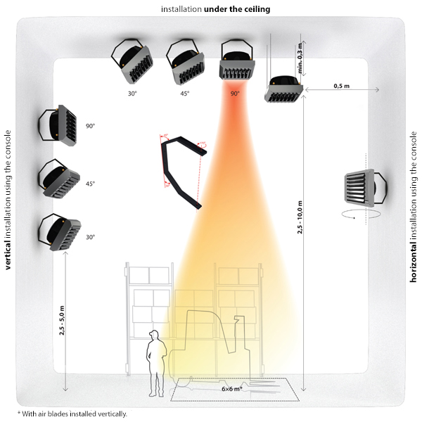
We present also some installation tips below:
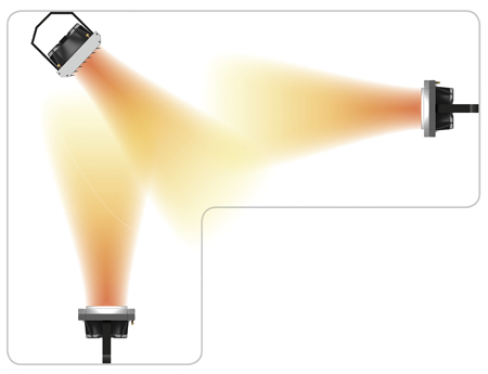
Steady air distribution should be provided in the entire room.
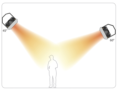
Correctly installed heaters should direct the air to the zone occupied by the people.
Heaters installed on the opposite walls should be overlapped.
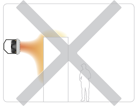
Big objects must not limit the air stream of the heater.
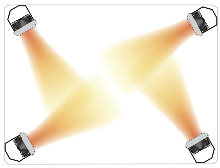
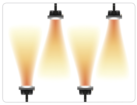
Heaters installed in the corners should direct the air into the center of the room to avoid “sticking” the air stream to the wall.
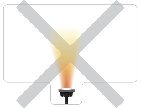
Heaters should be installed in a way that ensures free air supply around the unit.